kitspackman
Kit Basher
 Me and 'My' Canberra...
Posts: 97
|
Post by kitspackman on Dec 29, 2008 15:01:56 GMT
Colin, Those actuators are only applicable to the PR9, as it was the only mark with fully powered controls. (I have an idea the PR9 may have been the first RAF aircraft that was all powered too, not 100% sure about that though) Five will get you ten that Airfix used the same fin moulding for all of the different versions and left the actuator off as it would have meant a new mould just for the PR9. The powered controls were the bit of XH131 that I worked on in the 70s, fitting low contamination oil sampling valves in the aft camera bay. Naturally when I make my 1/72 scale version it will have a sampling valve in there as well........  |
|
|
|
Post by COLIN SHIPTON-KNIGHT on Dec 29, 2008 19:15:21 GMT
Kit, I know what you mean, I think they have made a few short cuts in this model. Understandable, but irritating... Have only just discovered a mistake on Airfix's part, and one of my own... Having another look at the instructions, regarding the Ailerons, and the 'missing' actuators. The instructions give this,  And then later the ailerons 'magically' appear with the actuators at the last stage of the instructions.  What is not highlighted is that the extra purely PR 9 sprue, has two replacement aileron upper halves, and that these should be used instead.  Having discovered my mistake in not noticing this in the first place, am now using kit number two, to replace the first set of ailerons I made..... Now they have the actuators on them and I no longer have to correct them, my mistake in the first place. However they still leave you with 'thicker' ailerons than the wing and they project below the wing, not hugely noticeable, but annoying. See previous post for photo. Have just put fuselage together... 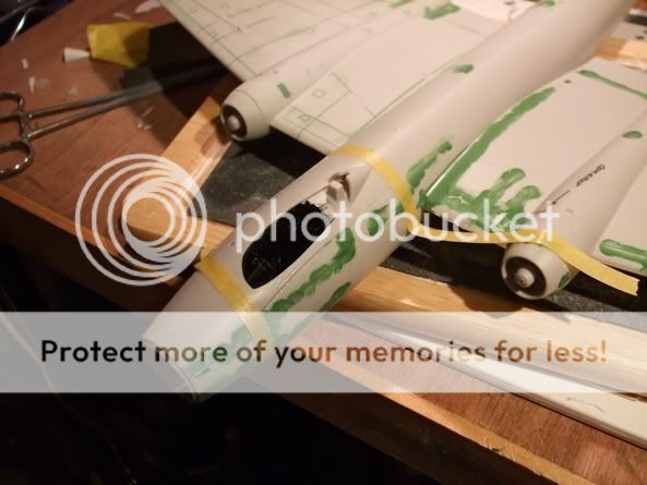 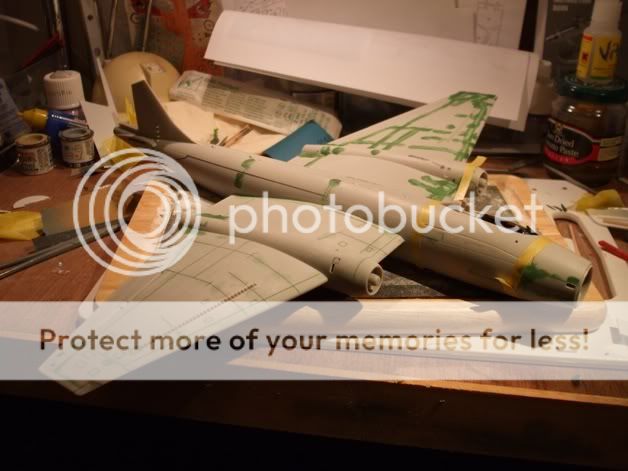 It leaves you with a rather awkward joint line either side of the cockpit, would definitely suggest a few dry runs to try this fit out, before gluing cockpit into a fuselage half, and then dry fit of halves, before trying to fit the panel from the top...... If that all makes sense? You may notice ongoing efforts to more accurately place Nav's window. Still struggling with what to do about 'Vortex generators' on upper wing. In reality they look about 1 inch high, which works out at approx 1/4 of 1mm high on model, and not rectangular but a trapezoid shape...! Love to hear any suggestions.... Am seriously thinking about sanding them off. |
|
|
|
Post by martinhale on Dec 30, 2008 2:58:30 GMT
You are going to have to live with generators that are a bit overscale but you can improve on the kit ones. This is what worked for me when I had to make some for my 1/96 scale Lindberg Victor.
Firstly remove the grossly overscale Airfix generators.
Secondly mark out as accurately as you can the position of the replacement generators.
Thirdly constructing a basic jig cut replacement generators from the thinest Contrail strut section. OK so they're no trapezoidal and it will drive you crazy glueing them all into place but they will look a whole lot better than what's in the kit. It looked OK in 1/96 scale so it should look much better in 1/48.
MArtin
|
|
|
|
Post by COLIN SHIPTON-KNIGHT on Dec 30, 2008 12:09:14 GMT
Martin,
Thanks for that, I was kind of thinking of something along those lines. I guess I'm going to have to have a practice run and see what it looks like....
Colin
|
|
|
|
Post by matzos on Dec 31, 2008 11:54:06 GMT
I have some shots of the PR9 on my site, www.airrecce.co.uk/graphics/AC/CPR9/cpr9_imagery.htmlI took these during their last deployment. I know that in my collect of CDs I have a number of close-up shots around the aircraft. Over the next week I will see if I can find it. Mick |
|
|
|
Post by COLIN SHIPTON-KNIGHT on Dec 31, 2008 18:42:57 GMT
Cheers Mick, any photos most welcome. The saga continues, fuselage together, starting to fill and sand all the 'trenches' that are on the model as 'panel lines'. It's a lot of work and I had forgotten just how much of a handful the model is when you have it in a sink using wet and dry... Rear fuselage just starting to mask out area of reinforcing plate. 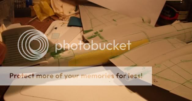 Starboard nose showing camera added to lower fuselage, and the rather awkward joint around the cockpit. Note repositioned Nav's window.  Port side, same comments. 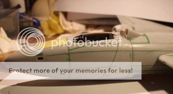 Overall view showing Navigator's Hatch being masked off.  Next steps being adding rudder actuator, correcting wing/flap area and having a go at modifying wing tips for most recent RWR gear... |
|
|
|
Post by COLIN SHIPTON-KNIGHT on Jan 2, 2009 20:23:54 GMT
Fin and Flaps...... Seemingly only minor problems to correct, but they have been driving me crazy the more I look at the kit, and photos and wishing that Airfix had done this themselves..... Fin first. Was hesitant about this at first, knew the profile was wrong, you only have to look at previous posts for that, but to sand the fin down and rearwards runs the risk of damaging the upper surface of the fuselage, something I did not want to do. Decided to tackle it with a file, just to get side profile correct first.  Did this rather carefully, trying not to file into the upper fuselage. Pleasantly surprised to find that there is a lot of plastic there, so you can be quite 'enthusiastic', and get back to nearer the correct profile.  Now I am happy about the profile, in comparison to the starting point, and happier that it looks more like it should, all I have to do now is 'round' it all off, but there is plenty of plastic left to left and right of centreline, so this should not be too difficult. 'Before and after'...  Flaps, problem outlined as previously... Firstly built up inner end of outer wing to correct position with plastic card glued under wing and filler on top. Look at green filler, it's only a small correction, but wait until you see finished product. 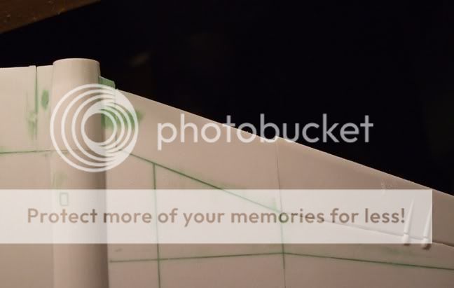 With a bit of gentle filing, to make room for 'strip' coming up... Original problem area...  Then offered up modified flap, that has thin card glued underneath it. 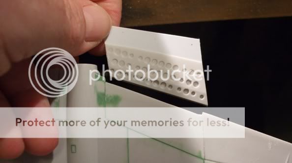 Leaving the card projecting backwards... 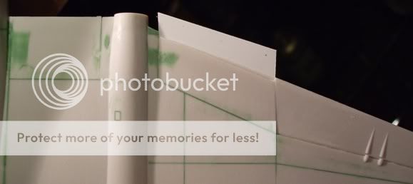 Then added tape, to show the correct line.  Then took flap away and cut to the line. Intention being to glue a strip of plastic to upper trailing edge of the flap, to not only correct profile, but add strip to upper rear flap, which is how it is on real aircraft. This can then be painted correct upper surface colour, at the rear of what is a white painted inside flap. If that makes sense...    Then offer up the modified flap to the wing, and lo and behold, it all looks right in shape and fit...   And when the flap is drooped, as it is on the ground...  You even end up with an easily painted strip on top of the flap, which is as it is on the aircraft..... Oh I am a happy bunny.... Things are progressing. Just got to do the rudder servo/actuator, the periscope, and those dreaded wing surface vortex generators, although I have found something that may well do it. My local model shop also caters for railway model enthusiasts, and they have plastic in all sorts of shapes and sizes. This should be good for cutting up and replacing those oversized 'lumps' on the wing.......  And then there is all the wet and dry work to get rid of the 'trenches' they call panel lines....... 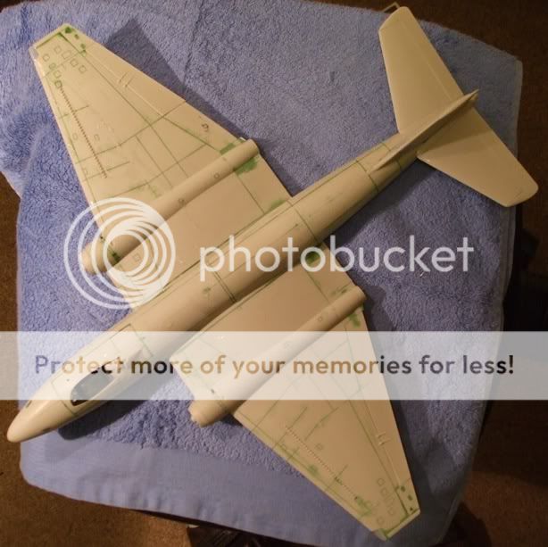 When I look at the panel lines on the Canberra and compare against the Nimrod I am also doing, I find myself wondering why Airfix could not have done the same on the Canberra, as they did so nicely on the Nimrod......... Till next instalment. |
|
|
|
Post by sloegin57 on Jan 3, 2009 0:19:00 GMT
Time for a bit of Techy Gen Colin. No doubt you have counted up the vortex generators to be manufactured - 33 per wing plus 8 for the fin = A LOT !! Unfortunately you have 8 more to do as Airfix forgot about the ones under the wing tip either side of the tanks. I seem to recall that the ones on the mainplane upper surface were smaller than the rest but I am not sure if it matters in 48th. I also seem to recall that they had swept leading edges. NB To other modellers Although the caption to the wing plan states 1/48th - it isn't, so that it fits in with the image size rules on the Web site. The fin diagrams are to 48th. I will mail you a full size 48th scan later Colin.  If you choose, you may have to re-profile the fin/rudder leading edge and top profile, see below:-   Attached a scan from a B.2 Vol.6 showing the correct fin profile (the leading edge fairing on yours looks the biscuit by the way).  I love Modelling, it's like Work, I could watch somebody else do it all day ;D ;D ;D You're going great so far Colin  Dennis |
|
|
|
Post by COLIN SHIPTON-KNIGHT on Jan 3, 2009 19:52:26 GMT
Dennis thank you for that, and the email... You are completely correct about the vortex generators under the wing tip, and I hope to do those on my models, however it leads me to a Question...... The tip tank on the PR 9 strikes me as slightly different than other marks. Obviously the wing tip is slightly different shape on a PR 9 than other marks. So was the tank modified as a result of this? Looking at a couple of your photos, I notice what appears to be a 'rail'/'pylon' on top of the tank, unlike anything else I have seen on other marks of Canberra...   I know it's small and difficult to see, but it is there... and it makes sense that they should be different, with the change in wing tip shape and profile, let alone the four 'vortex generators' under the tip. Any thoughts............. I am in a world of priming and sanding at the moment, not only the PR 9, but Nimrod R 1 and Korpen...... Colin |
|
|
|
Post by sloegin57 on Jan 3, 2009 20:33:59 GMT
Colin,
"rail?"/"pylon?" on top of tank ? - bit confused by that.
Tanks on the 9 were different to other Mks of Canberra but only in the fairings. Effectively mounted in the same place as other Canberras and also the same shape but as the tip extension "overhung" the tanks, the fairings were different.
By the by, forgot to mention that the tanks had vortex generators on as well - six each I think - I'll try and dig out some Pix.
Dennis
|
|
|
|
Post by sloegin57 on Jan 3, 2009 23:36:14 GMT
I'm not confused any more !!. After I had re-read your post Colin, I dragged the PR9 kit out of the shed and had a look. My worst fears were confirmed. It would appear that Airfix have used the standard tank from the B(I)8 kit and just plugged it into the PR9 mainplane which is totally incorrect for this marque of Canberra. The "rail/pylon" that you referred to was a stubb pylon/fairing that "hung" the tank clear of the mainplane on the PR9 although it was in fact part of the tank. It was not very deep as I recall but extended from the leading edge to the trailing edge of the mainplane at the point of attachment. I have cobbled together a montage of my photo's to show what I mean. I really must take a closer look at this kit as whilst I was checking the tank/mainplane fit I also notice that there is a pitot missing from the stbd nose, the extreme nose is too blunt, the LORAN aerial mounted above the port nwd has the locating dimples on the inside of the fuselage and none on the outside and the engine intakes are causing a bit of concern. That, together with the faults you have found plus the tanks are slowly turning this kit into a bag of nails - and I haven't looked at the cockpit and landing gear yet !!  . Nick (Southsix), I make no apologies if this image is a bit on the large size as I think that the info is important for anyone attempting this kit, Dennis |
|
|
|
Post by COLIN SHIPTON-KNIGHT on Jan 4, 2009 18:08:15 GMT
A bit further on, lots of wet and dry after first coat of primer to show areas that need more work. d**n vortex generators are driving me crazy..... Have tried doing a line of them on plastic card, cut from a length of profile, not easy... So resorting to plan A, I am attempting to file the kits generators into a thinner profile, by using a file with a smooth side resting upon the wing surface. you will be able to see slight marks on the photo from the file. I think it is only when it gets another coat of primer, that I will be able to tell how well this has worked. Have also removed wing tips along the panel line and glued plastic strip in it's place prior to sanding and filing the modified wingtip that the aircraft had late in it's service, with the Radar Warning Receivers at the front and rear of the tip.  Have also added the 'old' RWR on the fin, I have some shape issues with this and tried filing it closer to what I feel is right, before gluing on.  Have also added the actuator mechanism at the base of the fin and rudder, it's a small and fiddly shape to do... Bomb bay, have left this off until now, and the gap has provided a very useful handhold for all the sanding and working, after all it is a big model to handle.  Now this insert fits very well towards the rear, and towards the front, however the middle seems to be a little 'pinched' by the fuselage halves, so I think a spacer bar may well have to be glued across here, to allow the bomb bay insert to fit well, it is quite a stiff piece of plastic and is going to need some man handling and taping into place while glue sets. The green filler is me covering the forward camera position as it was not in use in the later version that I am doing. Suggest a few dry runs at this point after making sure you have plenty of weight inside to make sure it sits on its nose wheel. |
|
|
|
Post by COLIN SHIPTON-KNIGHT on Jan 4, 2009 18:31:11 GMT
Almost forgot... I can but recommend an excellent book on the PR 9, giving lots of information, lots of very good photos and a good breakdown of all the various mods between versions at different times in it's service. It also includes some good plans and drawings. Book has a slight bias towards the latter appearance of the PR 9's but is well worth buying.  |
|
|
|
Post by martinhale on Jan 5, 2009 13:44:26 GMT
Thanks for the bit on correcting the fin. Question does anybody know whst the inside of the large euipment hatch on the starboard side of the nose looks like and how it opens? It looks to me like if opened this would let more light into the fuselage and make any work done on the pilot's cockpit much more visible.
Martin
|
|
|
|
Post by sloegin57 on Jan 5, 2009 17:11:39 GMT
Good thinking Martin. Unfortunately that panel was the Main Equipment hatch which opened into the bay of the same name. It contained, on shelves (two or three I think), various pieces of radio and electrical equipment on which the various technicians performed their magic arts with wiggly amps and things. The panel itself was hinged at the top and opened by means of a single retractable handle. As I recall it was then supported by one or two struts which were clipped to the inside of the door when not in use.  The bay was behind the rear pressure bulkhead, on which the pilots seat was mounted and so opening up the hatch on the model would not let much light in. - in fact having finally got around to looking at the kit, Airfix have done a pretty good job of simulating the cramped conditions in the PR9. Even with the large canopy, the pilots position was quite crowded and the least said about the navigators slot the better. Dennis |
|
 Members' Forum")


