Members' Forum")


Post by bowman on Apr 22, 2013 14:04:46 GMT
My current project on the bench is a 1/24 scale scratch build of the JCB 410M-1C FLRT, which equipped my RLC Ammunition Squadron during the late 80's and throughout the 90's. The forklift was capable of travelling on roads at 35 MPH under its own steam and could also be towed behind an 8 tonner or similar, but as a result of some fairly hairy incidents in the early years, it was almost always transported as a flatrack load on the back of DROPS (elfin safety again...).
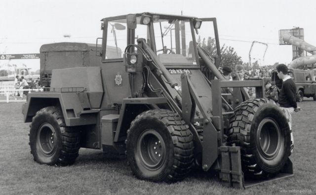
The forklift was powered by a Perkins 236-4T turbo charged 4 cylinder diesel engine, coupled to a Clarke-Hurth HR18000 powershift transmission which powered all four wheels. The vehicle steered by pivoting about a central point, just to the rear of the cab.
Not knowing any better, I started my scratch build with the engine. Common sense should have seen me trying to source wheels and tyres first, as these proved to be by far the most difficult parts so far. However, more of them later....
I'm sure that there will be a few kind souls out there that will point out some of the more obvious engineering inaccuracies of my engine and transmission, but as most of it will be hidden from view, I'll not lose too much sleep...
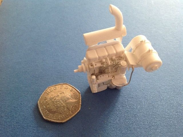
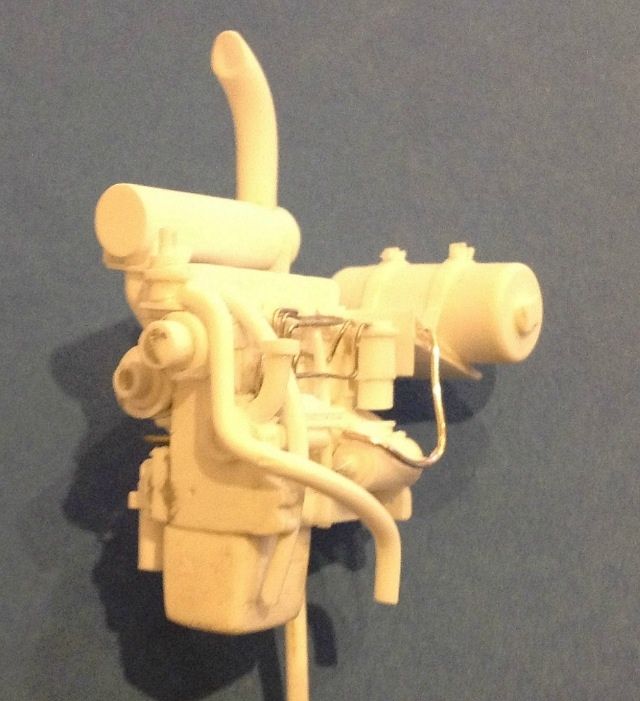
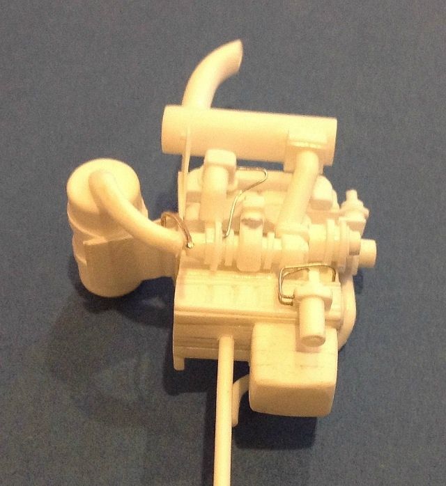
As anyone who knows me will attest, the fifty pence piece in the top photo was stolen from my wife's purse, because I never have any of my own. The large cylindrical tank at the front of the engine is the air filter and the pipe on top is the exhaust.
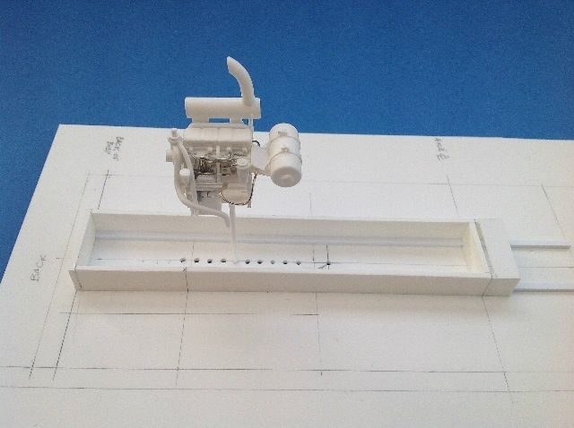
Having got the engine started, I then decided to produce a "setting out" board with all the major datum points shown. The two long rails are not part of the model as such, but indicate the minimum ground clearance for the vehicle.
Now, more about the wheels/tyres... In my relative naivety, I assumed that sourcing wheels and tyres in 1/24 scale would be fairly straightforwards, what with all the 1/24 scale truck models out there, and with there being two different pattern tyres in service. How wrong can you be! In the end, I had to get Gerry Mos to CAD model the early pattern tyre, a Michelin XLB 15.5-R20, which I then got 3D printed to form 5 tyres with wheels. When I first received these, they appeared to be the answer to a maidens prayer (not that I know many...) and, when coupled with two temporary simple axles, allowed me to set out the model a bit more.
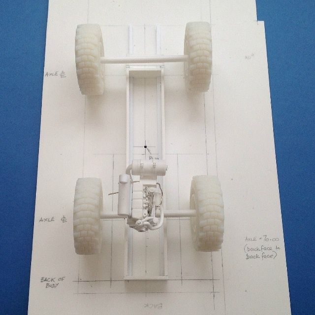
More of the infamous tyres later...
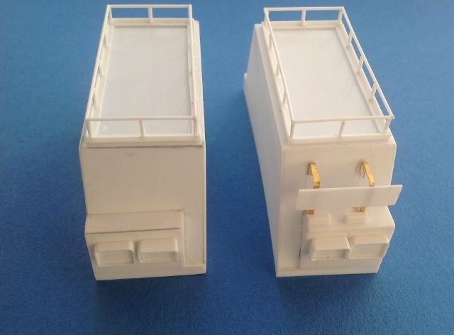
For no other reason than it seemed like a good idea at the time, I next decided to build the rear "bumper", which isn't a bumper at all, as it's made of a fairly think steel plate.
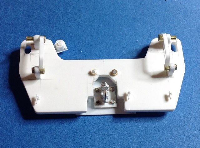
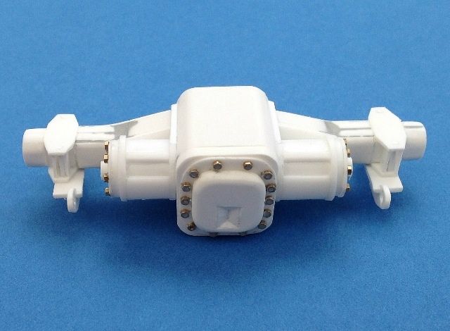
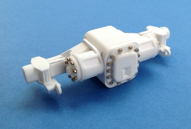
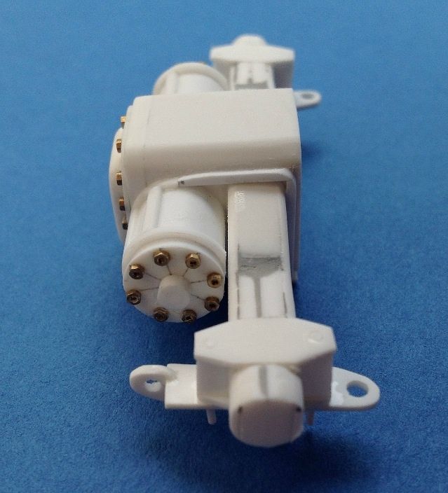
Having sorted out the rear most part of the build, I decided to fettle the most forward component (excluding the forks which were causing me nightmares) - the front axle.
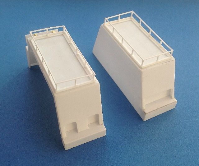
The rear wheel arches were next, as they helped to define the extent of the engine bay. Rear view first:
Then the side view:
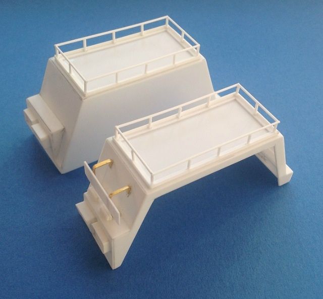
And finally the view from the front:
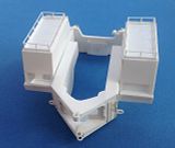
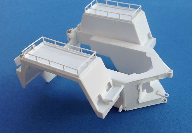
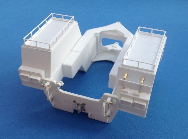
I next build the U shaped yolk that forms the rear chassis - sounds nice and simple when you put it in those terms, but it was a real pig! Still, with the wheels arches attached and the rear "bumper" fitted, the back half was starting to come together.
That's all for the present, more to follow shortly I'm afraid.
Steve

The forklift was powered by a Perkins 236-4T turbo charged 4 cylinder diesel engine, coupled to a Clarke-Hurth HR18000 powershift transmission which powered all four wheels. The vehicle steered by pivoting about a central point, just to the rear of the cab.
Not knowing any better, I started my scratch build with the engine. Common sense should have seen me trying to source wheels and tyres first, as these proved to be by far the most difficult parts so far. However, more of them later....
I'm sure that there will be a few kind souls out there that will point out some of the more obvious engineering inaccuracies of my engine and transmission, but as most of it will be hidden from view, I'll not lose too much sleep...


As anyone who knows me will attest, the fifty pence piece in the top photo was stolen from my wife's purse, because I never have any of my own. The large cylindrical tank at the front of the engine is the air filter and the pipe on top is the exhaust.
Having got the engine started, I then decided to produce a "setting out" board with all the major datum points shown. The two long rails are not part of the model as such, but indicate the minimum ground clearance for the vehicle.

Now, more about the wheels/tyres... In my relative naivety, I assumed that sourcing wheels and tyres in 1/24 scale would be fairly straightforwards, what with all the 1/24 scale truck models out there, and with there being two different pattern tyres in service. How wrong can you be! In the end, I had to get Gerry Mos to CAD model the early pattern tyre, a Michelin XLB 15.5-R20, which I then got 3D printed to form 5 tyres with wheels. When I first received these, they appeared to be the answer to a maidens prayer (not that I know many...) and, when coupled with two temporary simple axles, allowed me to set out the model a bit more.

More of the infamous tyres later...
For no other reason than it seemed like a good idea at the time, I next decided to build the rear "bumper", which isn't a bumper at all, as it's made of a fairly think steel plate.

Having sorted out the rear most part of the build, I decided to fettle the most forward component (excluding the forks which were causing me nightmares) - the front axle.


The rear wheel arches were next, as they helped to define the extent of the engine bay. Rear view first:

Then the side view:

And finally the view from the front:

I next build the U shaped yolk that forms the rear chassis - sounds nice and simple when you put it in those terms, but it was a real pig! Still, with the wheels arches attached and the rear "bumper" fitted, the back half was starting to come together.


That's all for the present, more to follow shortly I'm afraid.

Steve