|
|
Post by okdoky on Apr 25, 2013 11:09:24 GMT
Hi Steve Are they all designed with a degree of poseability ,,,,,,,,,, or are you playing safe with a final pose on delicate parts to preserve all that fine work  ? I found getting the rams to work right a real pain in the ass for the DROPS ,,,,,,,,,,,,, especially trying to shoe-horn them in and around all the other bits !!!!!! At least you have a fairly unclutered but still complicated engineering to work out all that geometry for the working parts !!!!!!!! Nice one |
|
|
|
Post by bowman on Apr 25, 2013 11:12:49 GMT
Everything is still poseable at present, but my plan is to fix things in place when all the parts are finished to make sure that all the angles stay "true".
This will be particularly important when I start fixing all the hydraulic pipes in place, as I've been unable to find anything flexible enough in the very small diameter that is needed. The small diameter pipes that fit to the actuators have a ribbed surface.
|
|
|
|
Post by okdoky on Apr 25, 2013 11:25:45 GMT
Would be good to keep the lifting poseable if you could !!!!!!!!! Slightly more options for display potential with the loads and the receiving vehicle !!!!!!!!! But always a dangerous choice if you get a nosey judge who tries to extend the forks and ends up taking half the vehicle with him !!!!!!!!!! I have heard it been done at many a show !!!!!!! I used to say to my brother "Do my wheels still go round ??" every time he used to ham-fistedly man-handle my latest build !!!!!!!! Normally I had one or more parts to put back on after he had been around !!!!!!! |
|
|
|
Post by okdoky on Apr 25, 2013 12:27:55 GMT
Maplins tend to have a real mix of cables and the like !!!! Might be worth while checking out some of the stuff they have that might be suitable if the wire taken out !!!!!!!
I now have a Maplins in Stirling, so might take a look see for my own sake as I want to see what they stock anyhow that might be of use in my builds !!!!!!!
|
|
|
|
Post by bowman on Apr 25, 2013 13:09:34 GMT
I've been thinking of doing the flexibles in tin plated copper wire wound with nylon fishing line. I haven't a clue whether it will look realistic enough, but will give it a try this evening (hopefully)...
|
|
|
|
Post by mossie on Apr 25, 2013 18:44:48 GMT
Love the build. Nice crisp detail and it is all from nothing, well loads of plastic and other things.
|
|
|
|
Post by bowman on Apr 25, 2013 19:14:21 GMT
Hi Gerry,
If it hadn't been for you pointing me at the Iron Planet web site and all the JCB photos it's doubtful whether I would ever been able to start the build. All I'm doing is cutting plastic - you did the intelligent bit by finding most of the research material!
Cheers. Steve
|
|
|
|
Post by bowman on Apr 26, 2013 7:25:44 GMT
Before I go too much further with this thread I need to explain the references to the "infamous wheels and tyres", and give credit to my good friend Gerry "mossie" Mos, that well known 3D CAD designer.
Gerry did some absolutely fantastic CAD modelling for my first set of wheels and Michelin XLB tyres. Unfortunately, the 3D printers that I used (no names, no pack drill) didn't quite live up to their previous reputation. The specification for this batch of printing called for exactly the same material that I've found to work in the past, printed at exactly the same resolution that has worked before. When the wheels and tyres arrived all appeared to be fine, that is until I got a coat of grey primer on them, when all the individual printed layers showed up in the tread, where I couldn't do much about it. It looked a right dog's breakfast!
Fortunately, I managed to acquire a set of the later pattern Michelin tyres that were fitted to the JCB (again, expertly designed by Gerry), and delivered courtesy of Howard at KFS and Nigel "Okdoky" Bisset, and they fit my JCB wheels a treat! A happy outcome to what could have been a complete and utter disaster!
Cheers. Steve
|
|
|
|
Post by bowman on Apr 26, 2013 7:55:20 GMT
I'm struggling a bit at the moment and am looking for some advice. On the three frames that make up the fork assembly there are three hydraulic actuators, each with two solid hydraulic pipes that then connect to flexible hydraulic pipes. At the cab end of this arrangement there is another collection of flexibles. My problem is sourcing suitable material for the flexibles, which don't need to be flexible at all on the model. 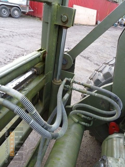 I tried thin wire wrapped round a thicker wire core and nylon line wrapped round a wire core, but neither of them looks right. Does anybody know of a suitable material or technique, or should I not worry and just use plated copper wire? The diameter of the pipes is 0.8mm at 1/24 scale. Cheers Steve |
|
|
|
Post by mossie on Apr 26, 2013 10:10:23 GMT
|
|
|
|
Post by bowman on Apr 26, 2013 12:19:43 GMT
Hi Gerry,
your Ebay link came up trumps. I've got some corrugated pipe on order which looks to be about perfect. I also had a tip from another forum which suggested using a low E guitar string. I've looked the images for this up on t'interweb and it also looks good, so I might try both and see which is best.
Thanks again for your help (at this rate it should be your name on the plinth rather than mine!)
Cheers
Steve
|
|
|
|
Post by mossie on Apr 26, 2013 12:40:21 GMT
No way, your making it happen.
|
|
|
|
Post by bowman on Apr 28, 2013 19:34:18 GMT
A good session today on forks and associated bits and pieces. 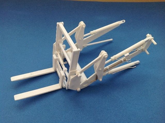 Ended up having to rebuild the fork frames (again) and the length of the lower hydraulic actuators is way too long, but progress none the less.... The rigid hydraulic plumbing on the fork arms turned out to be a bit more taxing than I initially thought. 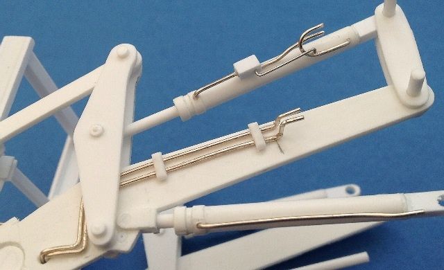 I couldn't resist dry fitting the forks to the front body section, just to get an idea of what it might look like in a few weeks time 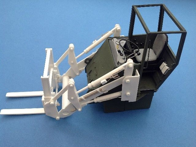 Finished off the day by fettling the steps into the cab 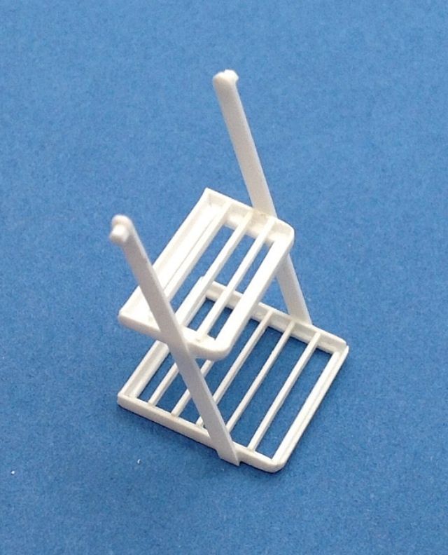 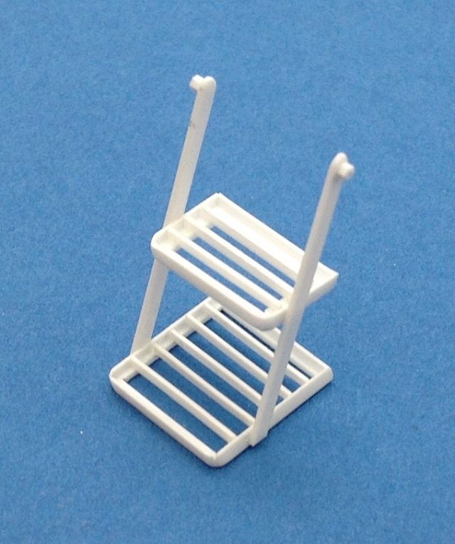 More to follow in a while. Cheers Steve |
|
|
|
Post by okdoky on Apr 28, 2013 19:57:40 GMT
STUNNING WORK IS ALL I CAN SAY !!!!!!!!!!!!
Nige
|
|
|
|
Post by bowman on Apr 28, 2013 20:40:05 GMT
Thank you Nigel
|
|
 Members' Forum")